|
ROTARY SAILS
Please use our A-Z INDEX to navigate this site where page links may lead to other sites
|
|
|
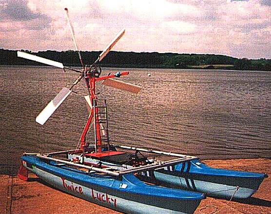
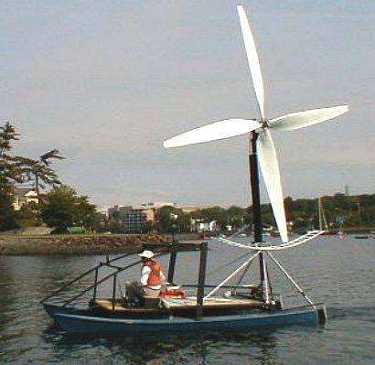
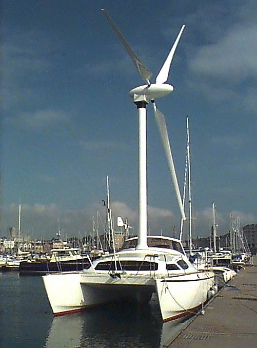
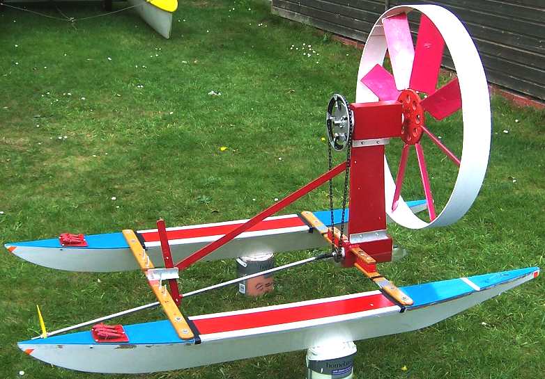
TWICE LUCKY - One of Peter Worsley's many superb experimental catamarans. They all worked to demonstrate the concept, with some showing the weaknesses of designs where the turbine was free to rotate, hence leading the way for other engineers to improve on.
The concept of rotary sails for boats as seen in several improved designs from 2015 to the present was patented by Peter Worsley in 1995 and granted in 1998, hence has expired under the 20 year rule that perplexes so many inventors, where copyright is free and lasts for 50 years after the death of the author - seriously discriminating against engineers.
Peter Worsley was a member of the Amateur Yacht Research Society in the UK, being particularly interested in promoting wind power for yachting, including vertical rigid sails. As with many innovators he was years ahead of his time. Only now is there any possibility of use of rotary sails for shipping due to the climate emergency.
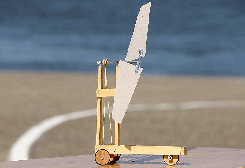
The same technology has been applied to vehicles called land yachts. There are notable examples of land yacht projects two of which are useful in relation to boat projects.
ROTOR POWERED VEHICLES
Rotor-powered vehicles are wind-powered vehicles that use rotors - instead of sails - which may have a shroud around them (ducted fan) or constitute an unducted propeller, and which may adjust orientation to face the apparent wind. The rotor may be connected via a drive train to wheels or to a generator that provides electrical power to electric motors that drive the wheels. Other concepts use a vertical axis wind turbine with airfoils that rotate around a vertical axis.
THEORY
-
Likewise, there is no theoretical upper limit to how fast a rotor-driven craft can go directly downwind.
- Two masses moving with respect to each other, e.g. the air (as wind) and the earth (land or water).
- The ability to change the velocity of either mass with a propellor or a wheel.
In the case of a rotor-powered vehicle, there is a drive linkage between the rotor and the wheels.
Depending on one's frame of reference - the earth's surface or moving with the air mass—the description of how available kinetic energy powers the vehicle differs:
-
As seen from the vantage point of the earth (e.g. by a spectator), the rotor (acting like a wind turbine) decelerates the air and drives the wheels against the earth, which it accelerates imperceptibly.
In 2009, Mark Drela—an MIT professor of aeronautics and astronautics—produced the first equations, demonstrating the feasibility of "Dead-Downwind Faster Than The Wind (DDWFTTW)".
Other authors have come to the same conclusion.
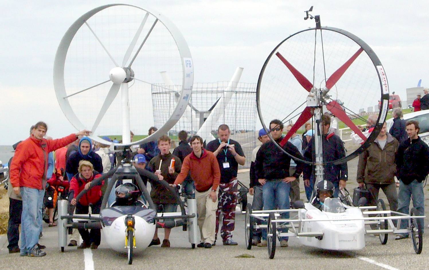
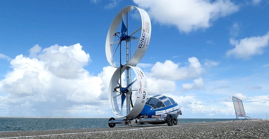
RACING AEOLUS - ROTARY SAIL DRAG RACE 2014
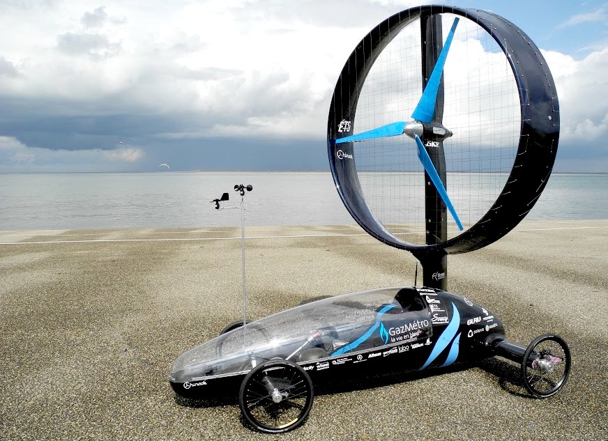
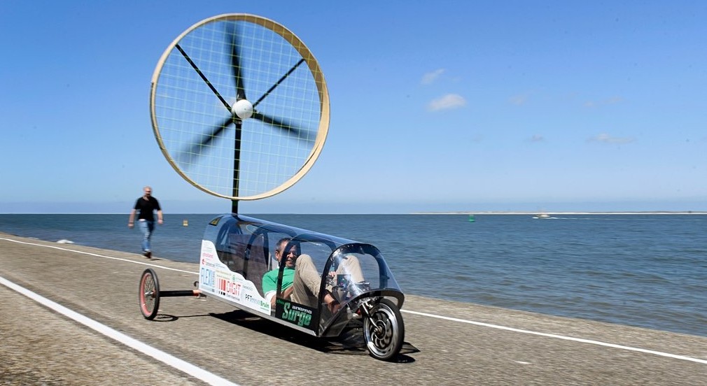
In 2012, Chinook ETS were the champions at Racing Aeolus. in 2013, they set the record with a vehicle speed of 82.6% of the wind speed while heading into the wind. This last August was even better.
CHINOOK 2019
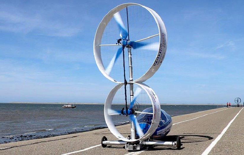
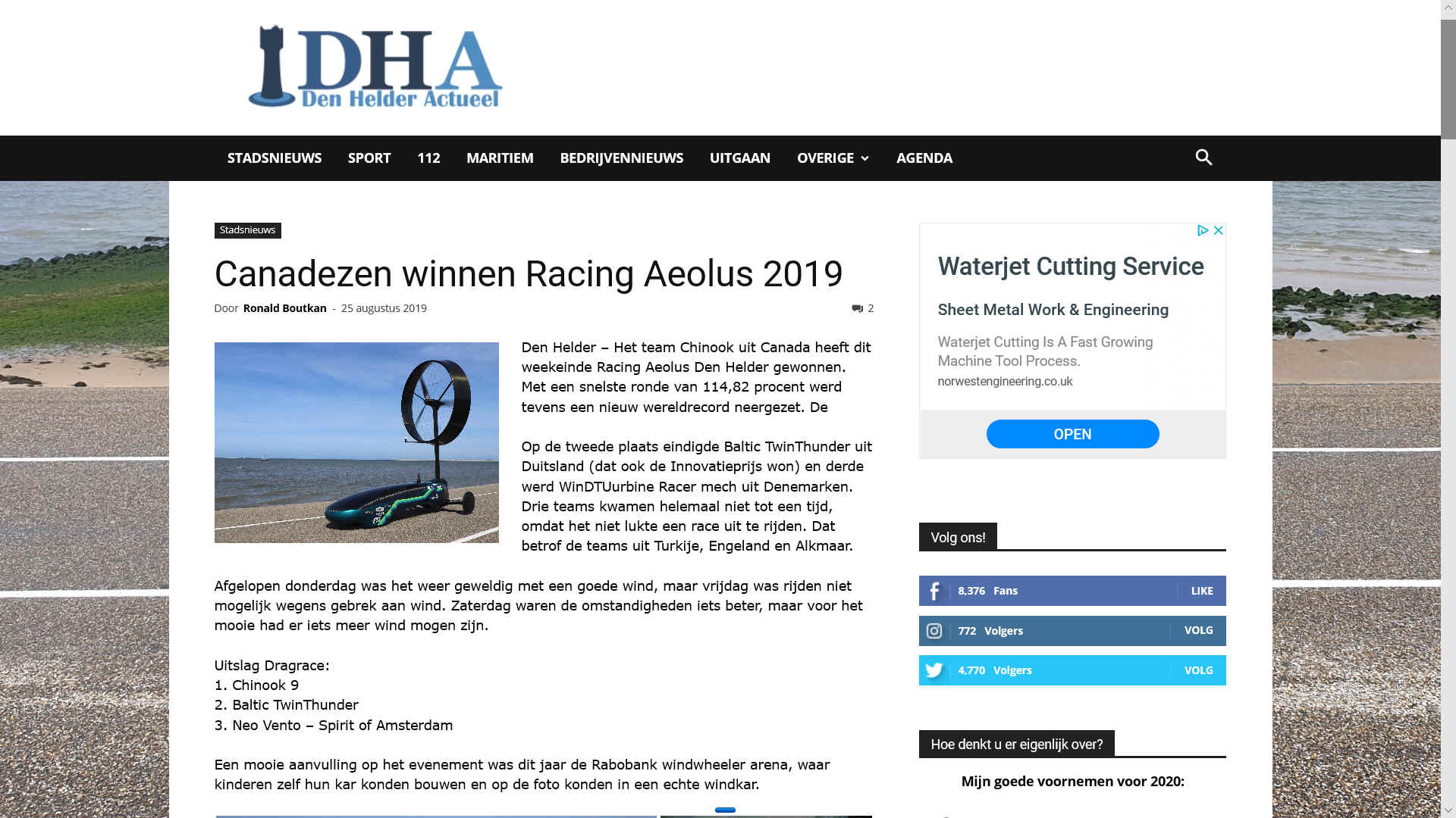
Den Helder - The Chinook team from Canada won Racing Aeolus Den Helder this weekend. With a fastest lap of 114.82 percent, a new world record was also set.
The Baltic TwinThunder from Germany (which also won the Innovation Prize) finished in second place and WinDTUurbine Racer mech from Denmark came third. Three teams did not come to a time at all because they were unable to complete a race. That concerned the teams from Turkey, England and Alkmaar.
BLACKBIRD
The Blackbird is an experimental land yacht, built to demonstrate that it is possible to sail directly downwind faster than the wind.
BLACKBIRD TECHNICAL
PATENTS - WIND POWERED CRAFT IMPROVEMENTS IN & RELATING TO
Description
This invention relates improvements in or relating to wind powered craft and is concerned with a wind powered drive means for use in a water or land-borne vehicle. More particularly the invention relates to a wind-turbine including a plurality of blades mounted on hub assembly which is rotatable with respect to a mast and wherein the blades and hub provide for drive to a means serving to propel the craft relative to water or land.
Attempts have been made in the past to provide a boat with a mast carrying a propeller assembly which is driven by the wind to thereby transfer power through a shaft to drive a conventional propeller positioned in the water at the stern of the boat. The disadvantage of such constructions is that a wind vane is required for alignment of the turbine in the most favorable direction and the turbine itself incorporates a plurality of thin blades which are designed to produce the required drive at relatively high rotational velocities which makes progress towards the direction of the wind difficult to achieve.
It is another object of this invention to provide an improved construction with a controllable drive that will allow a water-borne or land vehicle to travel directly to windward more effectively.
A further advantage of this construction is that a wind vane is not required but, in practice, some form of counterbalance is necessary to avoid rotation about the vertical axis following a tilt in the mast from a vertical position, for example due to a water borne vehicle heeling over. In an alternative aspect of this invention or as a preferred feature of the invention set forth above, there is provided a wind powered drive means for a vehicle and including a rotatable turbine assembly mounted to the top of a mast with drive means coupling said assembly to a further means for propelling the vehicle, the turbine assembly including a hub with a plurality of low velocity sails extending therefrom and wherein the sails are rigged to provide an angle of pitch relative to the oncoming wind direction when stationary of not more than about 450.
With such a construction the sails will revolve at a slower speed than the wind and in order to compensate for such slow speed the sails have a greater area than the blades or sails used in known constructions.
The two aspects of this invention referred to above may be utilised either individually or in combination.
This invention and further and preferred features thereof are described hereinafter in more detail and with reference to practical constructions which are also illustrated diagrammatically in the relevant figures of the accompanying drawings.
Figure 1 shows diagrammatically and in side view a water-borne vessel as a first embodiment, Figures 2a to 2d show in plan view the vessel of Figure 1 in four directions relative to the prevailing wind, Figures 3a and 3b show diagrammatically by vectors the different forces on two blade designs, Figure 4 shows a side view of a second embodiment of water-borne vehicle, Figure 5 shows a third embodiment constructed as a trimaran, but omitting the outboard hulls, Figure 6 is a front view of the embodiment of Figure 5, Figure 7 shows a fourth embodiment with modified drive means, Figures 8 and 8a show a fifth embodiment comprising a catamaran modified to incorporate a drive according to this invention, Figure 9 shows a sixth embodiment comprising a land vehicle, and Figure 9a shows a detail of the belt drive of Figure 9.
Although many of the embodiments hereinafter disclosed relate to a water borne vehicle, which is to be powered by the wind, it is to be understood that features in the construction can be adopted and adapted mutatis mutandis in a construction used for propelling a vehicle on land.
According to this invention in one aspect revolving sails are used, which could be described as a slow speed wind turbine, or wind rotor. These sail blades are connected through gearing to a water-screw which drives the vessel.
There have been prior attempts to power a vessel in this way, but these have not been successful as they have used small area, fast rotating blades, whereas the system according to this invention uses blades of many times greater area than used before, which rotate at a slower speed. This provides several advantages, and it has been found, by tests on models, that it makes motion directly into the wind much easier to achieve than any prior known method.
Referring to Figure 1, the mounting mast 1 is fitted to the hull 15 of the vessel to coincide with the centre of lateral resistance. The rotor assembly 2 is attached to the mast 1 in such a way that it can rotate about a vertical axis at pivot 8. The axle 3 of the turbine blades 4 is of sufficient length to enable the turbine to be some distance behind the mast 1 (relative to the oncoming wind). In this way, the aerodynamic drag of the turbine, plus the side, area of the turbine assembly, ensures that the turbine head follows any changes in the wind direction automatically.
In order to prevent the turbine assembly falling to one side if the vessel heels, an arm with a counterweight 7 is fitted to counterbalance the weight of the turbine assembly.
rive to the water-screw 10 is achieved by use of a belt (not shown and possibly toothed). A belt is used between pulleys 6 and 12 as it has been found that use of a vertical drive-shaft results in torque which would cause the rotor head to twist and move the blades away from their best position relative to the wind direction.
The belt drive here used has the disadvantage in that it cannot be twisted more than a certain degree, because it would come into contact with the mast mountings, therefore the rotor assembly is only allowed to swivel 1800, that is, with the wind 900 either side of the straight ahead position.
This means the vessel could travel by using its rotor only between the wind-abeam position on one side, through the wind-ahead position, to the wind-abeam position on the other side (see Figure 2a to 2d).
Pulley 12 drives screw 10 through a universal joint 9. The blades 4 of the turbine may be adjustable in pitch by means of a control assembly 5. The blades here are shown feathered.
A stop such as line 11 may be arranged to prevent the rotor-head swivelling further than the wind-abeam positions. Downwind sailing is achieved by merely using the drag of the rotor head assembly to push the vessel along. In downwind sailing, the rotor will cease to turn because, due to the stop, it can no longer face the wind.
Although this could mean that the downwind performance of the vessel might not be optimum, this is outweighed by the advantage of the impressive upwind performance, and the automatically adjusting rotor head.
For a vessel to make progress directly into the wind which is used as a driving force, it is necessary for the rotors to develop more driving force, or lift, than the drag or windage of the whole craft. The drag of the hull, superstructure and mast is only part of this drag, a certain proportion of the lift of the rotors themselves will oppose the movement of the vessel towards the wind.
This axial force will depend upon how fast the rotors turn relative to the wind speed. If the rotors are of a high speed type, as shown in Figure 3b, then because of their speed, they must be angled very squarely to the direction of motion and this causes most of their lift to retard the craft.
This drawback is partially overcome by the mechanical advantage (leverage) of their high speed relative to vessel speed, but it means the speed of the blades, and consequently the stresses upon them, are very high.
When sailing directly into the wind, the fast-spinning high speed rotor, although it is producing more lift because of its large angle to the direction of travel, most of this lift actually holds the vessel back, whereas in the case of the large slow blade of Figure 3a, most of the lift can be used as driving force to push the vessel to windward.
With slow speed blades, a much greater proportion of the lift produced can be used to propel the craft, with the only disadvantage being that they must be of greater area because, due to their lower speed, their leverage is less.
Experiments have been made with various blade angles, number of blades, and blade area, and in a particularly successful working model there is provided a six-bladed rotor with blades at 400 to the oncoming wind when the rotor is stationary. Although the water-screw is of large area it still means it must spin at more than three times the speed of the rotor. It has been found that the gear ratio between the rotor and the water-screw is important, and on a full size vessel, could be as much as 1:8 The blades themselves are of open frame construction, fabric or plastic covered, similar to aircraft wings, but of lighter construction. Any aerofoil section may be used, from symmetrical to curved "slow speed" types.
The low speed blades have several advantages as follows:
1. As the blades only turn slowly, there is little danger of them over-speeding in high winds and at 400 angle the blades cannot turn faster than the wind speed.
2. The stress upon the blades is small, and therefore they can be made light and of low cost.
3. With the wind on the beam, the heeling force is much less than on a conventional sailing craft, or a vessel with a high-speed wind turbine. This means a much larger blade area can be carried without capsize.
4. With the craft at anchor, the rotor can be disconnected from the water-screw and used to power a generator for general use or to recharge batteries for use in windless conditions.
On a full size practical construction of craft according to this invention, some means of controlling the power from the rotor would be necessary. To this end, the rotor blades are made to be able to vary their pitch. The angle of the blades can be varied, by means of a lever or rope between 400 for maximum power and a 00 feathered position. Gearing between rotor and water-screw may be made variable, or alternatively a variable pitch water-screw used.
When the blades are feathered the rotor assembly should cause very little wind-resistance as it will automatically swing to align itself with the wind direction. This would be useful for riding out high winds. The blades should also be easily removable for protection from the weather when the vessel is not in use.
Figure 4 of the accompanying drawings shows a further construction in side elevation wherein the drive 40 (shown in outline only) from the rotary sail assembly 41 is taken to a water screw located on the central keel 43 of a water craft 44.
Although the previously described constructions relate to a belt drive system between the turbine assembly and the water screw, in a modification a chain driven means may be used.
Figure 5 of the drawings shows a further construction in side elevation and wherein two drive belts are used. Referring to the drawing, the sails 50 which are mounted on hub 51 have a symmetrical aerofoil section and drive a pulley 52 through shaft 53. This assembly is mounted for rotation about a vertical pivot 54 on the top of the mast structure 55. A counterbalance arm and weight assembly 56 is provided.
The pulley 52.drives a lay shaft 56 through a belt and via pulley 57. The lay shaft 56 in turn is provided with a forwardly located pulley 58 which drives, via a further belt, pulley 60 mounted on drive shaft 61 connected to the water screw 62. This arrangement provides for more flexibility in the location of the water screw shaft. In a further constructional arrangement, a gear box unit may be provided within the drive train to provide a variable rotational speed of the water screw.
Figure 6 shows a front view of the embodiment of Figure 5 illustrating the path of the drive belt between pulley 52 and pulley 57 and the drive belt between pulley 58 and pulley 60. This drawing also illustrates spring loaded roller 63 which serves to maintain appropriate tension in the drive belt.
Figure 7 illustrates a further construction wherein the drive is applied to the inboard end of a canted water screw drive shaft. As shown, the drive from pulley 52 is transmitted via the drive belt 70, to pulley 71, connected to the inboard end of drive shaft 72 which carries the water screw 73. In order to provide for the angular difference in the plane of the pulleys 52 and 71, a transverse jockey pulley construction 74 is provided beneath the vertical pivot on the mast 55. Another method of taking care of a canted drive shaft 72 is to provide a universal coupling or constant velocity joint such as is illustrated by reference 9 in Figure 1.
Where a chain drive system is in use, then a chain tensioner comprising a toothed sprocket or runner device may be incorporated into the construction.
Referring now to Figures 8 and 8A of the drawings, these show the constructional unit which may be mounted on an existing catamaran in order to replace the usual sail assembly with a rotating sail drive according to this invention. Referring to Figure 7 and 8, a carrier unit 170 comprising a linked framework is adapted to be mounted on and located across the two hulls 171 of a catamaran with a keel and drive unit 172 carried by the framework 170 and positioned in the water between the two hulls. The keel unit 172 incorporates a water screw 173 mounted on drive shaft 174 with pulley 175 connected via a belt drive 176 with pulley 177 on a further lay shaft 178. The lay shaft 178 includes a pulley 179 which, via a further belt drive 80, connects with pulley 81 mounted at one end of shaft 82, the other end of which carries the rotatable sail assembly 83. The framework includes mast 84 to which a carrier for the sail assembly 85 is connected through vertical pivot 86. The construction and operation of this arrangement is substantially identical to that hereinbefore described but is particularly adapted for conversion of an existing catamaran. It is also envisaged that a monohull construction of sail boat could be adapted in a similar manner although the addition of outriggers of some kind would be desirable in order to prevent excessive heeling.
In all of the constructions described the rotor head carrying the sail structure may be locked relative to the vertical support mast. With such an arrangement, when unlocked the vessel may be directionally steered independently of the wind direction and hence the angular relationship between the sails of the rotor and the wind but when locked, the vessel will steer according to the prevailing wind direction, thus providing a self-steering effect.
In a further embodiment and extension of this invention, and as shown in Figure 9 and 9a, a wheeled land vehicle 90 is provided which incorporates the same general structure for the rotatable sail assembly 91 but where the structure drives the wheels 92 of the vehicle, preferably through belt means 93 as shown in the drawing.
Due to the low rotational speed of the sails 91 in accordance with the construction adopted by this invention, direct drive via pulleys 94 and the belt is possible to the rear wheels 92 of the vehicle. The drive is shown in more detail in Figure 9a.
Conveniently, a gear box may be incorporated within the gear chain and in simpler constructions, a chain drive may be adopted using a derailleur kind of unit to effect changes in the drive ratio. A conventional kind of differential may be provided for the coupling between the two rear wheels. As an alternative, free-wheel units could be incorporated into each rear wheel or drive may be taken to one rear wheel only Experiments have shown that a vehicle of this kind accelerates very quickly when wind speed picks up but also de-accelerates just as quickly when the wind lulls due to the braking effect of the large area sails. This disadvantage can be overcome by providing a suitable freewheel means in the drive chain, thereby allowing the vehicle to coast between gusts if required. Such a construction may be also incorporated into the water borne vehicle previously described.
Figure 3 of the drawing is a comparison between a fast rotating high speed blade and a much larger area blade which is rotating slower and on a vessel which is attempting to make a progress directly into the wind.
The fast spinning blade, in order to produce lift, must be set so that its angle of attack is approaching 900 to the desired direction of travel. Although the lift produced may be greater than that of a slow blade, the lift is mostly counter productive because it opposes the intended direction of the craft, and is a retarding force. Only a small proportion of the lift produced can be used to make the blade rotate, and even this small amount must be used to overcome the retarding force, before any that is left over can be used to drive the vessel. It is true that this disadvantage can be partially overcome by the fact that the blade moves at a much greater speed than the craft, and thus mechanical advantage is obtained, but the forces involved are very high.
In the case of the larger slow-speed blade, the driving force is much greater than the retarding force and therefore there is still plenty of power available to drive the vessel into the wind. The gear ratio between the blades and the vessel (or landcraft) drive is naturally adjusted for the best possible result. The greater effectiveness when travelling to windward of large slow blades over the hitherto used high speed type has been proven by practical experiment.
As well as being the prime source of power for a vehicle the drive means according to this invention may be used as an auxiliary power drive with the main source being a motor or conventional sails.
To achieve downwind running the blades can be locked against rotation and they thus form a sail structure.
In a modification the rotor head carrying the blades may be fixed and the aerodynamic side area located well behind the centre of lateral resistance. With this arrangement the vessel aligns into wind at all times and is useful as an upwind tug to prevent a free floating vessel moving downwind. An increase in wind velocity producing a corresponding increase in tugging force.
CLAIMS
a) a mast assembly for mounting in a substantially vertically projecting position from the vehicle,
b) a hub rotatably mounted about a horizontal axis on an upper end part of the mast,
c) a plurality of sails or blades extending from said hub and forming therewith a turbine structure,
d) the turbine structure being mounted to the mast to be rotatable around a vertical axis thereon,
e) the plane of rotation of the sails or blades being horizontally distanced from the mast,
f) a first drive means coupling the turbine structure to the upper end of the mast,
g) second drive means coupling said first drive means to the base of the mast,
h) third drive means coupling said second drive means to means capable of propelling the vehicle,
i) said first, second and third drive means being constructed and arranged so that drive torque reaction does not occur around the vertical axis of mounting the turbine structure to the mast.
USA - Professor Brad Blackford sailing his experimental boat.
GB2286570A
-
1994-02-15 -
1995-08-23
AEOLUS CONTACTS
If you want to contact the foundation Wind Energy Events please send an e-mail to the chairman Hans Verhoef:
hans.verhoef@tno.nl
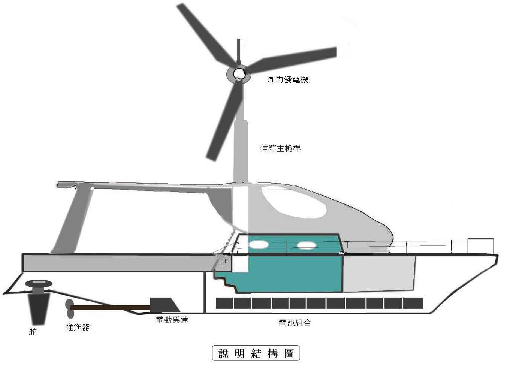
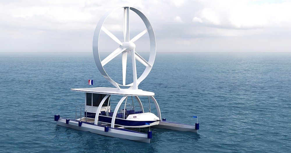
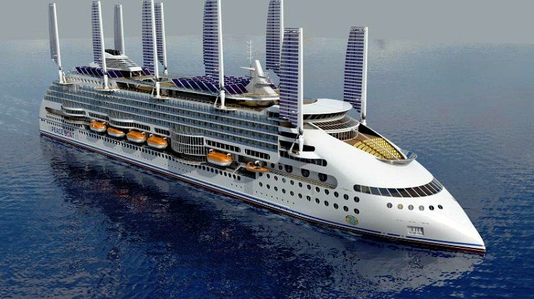
Wind powered electric catamaran as an artists impression, presumably from CAD drawings. The wind turbine is a nice design.
ROTARY WIND POWER: A daring conversion; wind turbine powered catamaran, the Revelation II. We'd like to feature more on this vessel if the owner would care to get in touch.
A - Z SAIL AND SOLAR ASSISTED BOATS & SHIPS
LINKS & REFERENCES
https://www.ipo.gov.uk/p-ipsum/Case/PublicationNumber/GB2286570 https://en.wikipedia.org/wiki/Wind-powered_vehicle https://denhelderactueel.nl/2019/08/canadezen-winnen-racing-aeolus-2019/ https://solarimpulse.com/companies/archinaute-fr http://www.archinaute.fr/actualite%202017-2018.html https://www.ouest-france.fr/bretagne/belz-56550/belz-archinaute-le-bateau-eolien-grandeur-nature-6342767
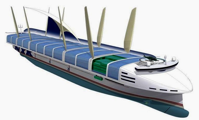
TRANSFERABLE TECHNOLOGY - The design of the Climate Change Challenger might be adapted to Cargo, Container, Cruise and Ferry designs, without needing to radically alter port facilities. The designs above are not representative of adaptations of the concept, but serve to illustrate the thinking of other design houses.
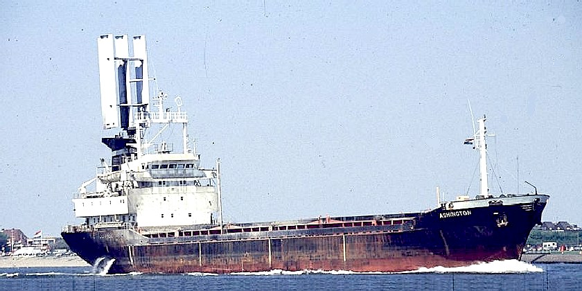
WINGSAIL ASSISTED SHIP 1987 CONVERSION - This cargo vessel started life as the Ashington, registered at London in 1979. She is notable for her distinctive computer controlled wing-sails. It is a real shame that this pioneering vessel was scrapped, rather than preserved by way of an example of industrial archaeology in action. One way to chart our future is to reflect on the past. The small wing area should be roughly tenfold to take diesel engines out of the frame. Replacing with rotary sails might reduce the area needed for the same propulsion.
Please use our A-Z INDEX to navigate this site
AEGEAN - ADRIATIC SEA - ARCTIC OCEAN - ATLANTIC OCEAN - BALTIC SEA - BAY OF BENGAL - BERING SEA - CARIBBEAN SEA - CORAL SEA EAST CHINA SEA - ENGLISH CHANNEL - GULF OF GUINEA - GULF OF MEXICO - INDIAN OCEAN - IONIAN - IRISH SEA - MEDITERRANEAN SEA NORTH SEA - PACIFIC OCEAN - PERSIAN GULF - SEA OF JAPAN - SOUTH CHINA SEA - SOUTHERN OCEAN - TYRRHENIAN
|
|
|
This website is provided on a free basis as a public information service. copyright © Climate Change Trust 2020. Solar Studios, BN271RF, United Kingdom.
|